




Functional Validation
Review fit, interfaces, fastening, handling, and assembly sequences with representative prototype molded parts.
Capabilities
CNC MachiningCNC milling, 5-axis machining & CNC turning› 3D PrintingSLA, MJF, SLS & DMLS 3D printing› Vacuum CastingSilicone mold making, urethane casting & vacuum-cast prototypes› Sheet Metal FabricationLaser cutting, bending & welding› Injection MoldingLow-volume, insert & overmolding› Rapid ToolingPrototype tooling for molded-part validation› Die CastingAluminum, zinc & magnesium die casting› Metal StampingPrecision & progressive stamping› Surface FinishingBlasting, anodizing, plating, coating & polishing›CNC Machining
Browse by Material
AluminumLightweight, corrosion-resistant aluminum for CNC-machined prototypes, brackets, housings, and precision parts.› Stainless SteelCorrosion-resistant stainless steel for CNC-machined components, tooling, and parts used in clean or demanding environments.› SteelVersatile steel for CNC-machined structural parts, fixtures, shafts, brackets, and production tooling.› ZincZinc for compact die-cast housings, hardware, and detailed industrial components where fine detail matters.› CopperHigh-conductivity copper for electrical contacts, connectors, heat-transfer parts, and precision components.› BrassMachinable brass for fittings, valves, electrical hardware, bushings, and precision turned parts.› TitaniumHigh-strength, lightweight titanium for aerospace, medical, and performance-critical machined components.› MagnesiumUltra-lightweight magnesium for weight-sensitive housings, structural components, and machined prototypes.› BronzeWear-resistant bronze for bushings, bearings, marine hardware, and sliding mechanical components.› IronDurable iron for fixtures, tooling, structural components, and wear-focused industrial applications.› ABSImpact-resistant ABS for machined prototypes, housings, fixtures, and functional appearance parts.›Rapid Tooling Services
Use prototype injection molding to validate fit, assembly, material behavior, and manufacturability before committing to production tooling.
Process Overview
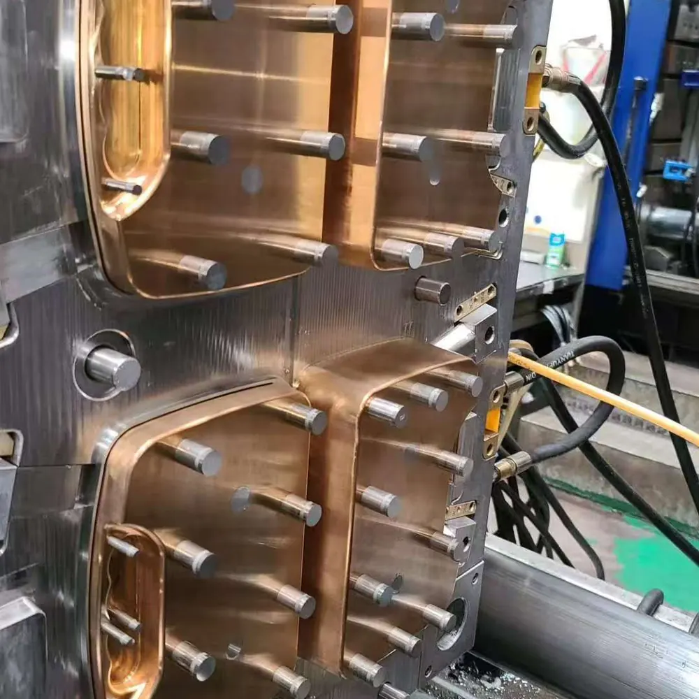
Prototype tooling is a purpose-built mold solution for producing representative prototype injection molded parts before production tooling is finalized. It gives engineering teams physical evidence for design, fit, assembly, material, and functional review.
The appropriate prototype mold is defined by part geometry, resin selection, planned quantity, cosmetic requirements, critical interfaces, expected revisions, and the decisions each sampling round must support.
Why Choose Prototype Tooling?
Review fit, interfaces, fastening, handling, and assembly sequences with representative prototype molded parts.
Assess selected resin options, visible surfaces, texture direction, color targets, and user-facing part behavior before later tooling decisions.
Identify draft, wall-transition, gate, venting, ejection, and undercut considerations while design changes remain manageable.
Use defined sampling rounds to refine geometry, critical dimensions, inserts, cosmetic areas, and functional details with measurable feedback.
Use prototype mold results to guide production-tooling strategy around validated requirements, expected demand, revision risk, and program timing.
Carry approved CAD, material, inspection, and process learnings into the next tooling or manufacturing stage with clearer technical alignment.
How It Works
Review 3D CAD, drawings, resin selection, target quantity, cosmetic surfaces, critical dimensions, and validation goals.
Assess moldability and define the parting strategy, gates, ejection, cooling, inserts, and expected revision approach for the prototype mold.
Machine, prepare, and assemble approved mold components according to the agreed prototype tooling plan.
Run prototype injection molding trials to establish stable filling, packing, cooling, and part-release conditions.
Review dimensions, assembly interfaces, surface condition, and functional results, then implement agreed part, tool, or process adjustments.
Inspect approved prototype molded parts against the agreed requirements, prepare the required records, and package samples for delivery.
Mold Structure Options
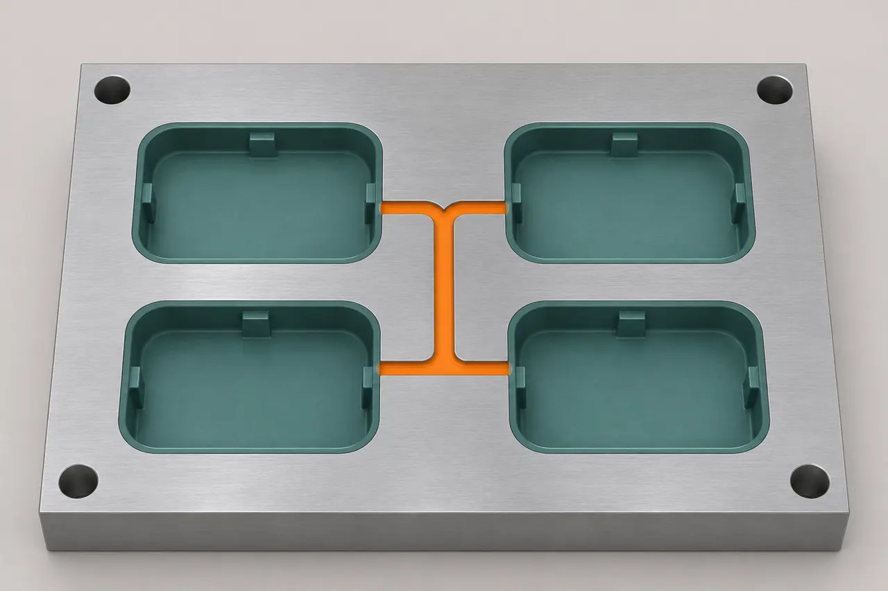
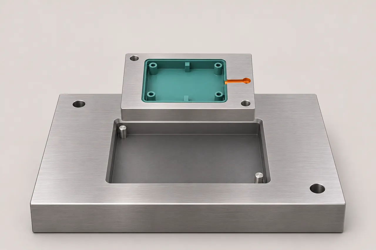
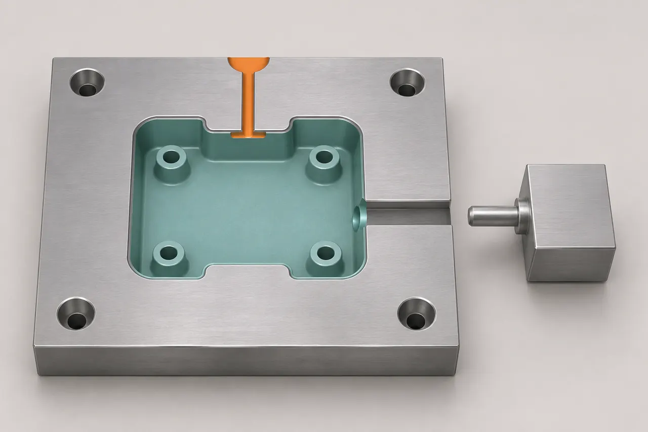
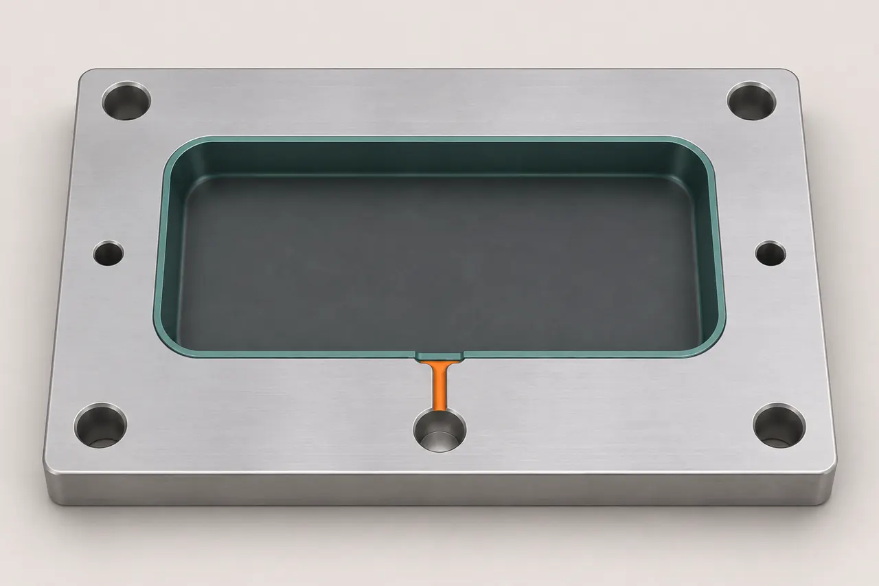 Illustrative mold layouts; not construction drawings.
A prototype mold structure that produces one part per molding cycle, giving teams a controlled route for functional samples, design changes, and early production learning.
Engineering Before Tooling
Before prototype mold making begins, the part design and tooling concept are reviewed as one system to identify molding risks, prioritize validation needs, and keep expected changes practical.
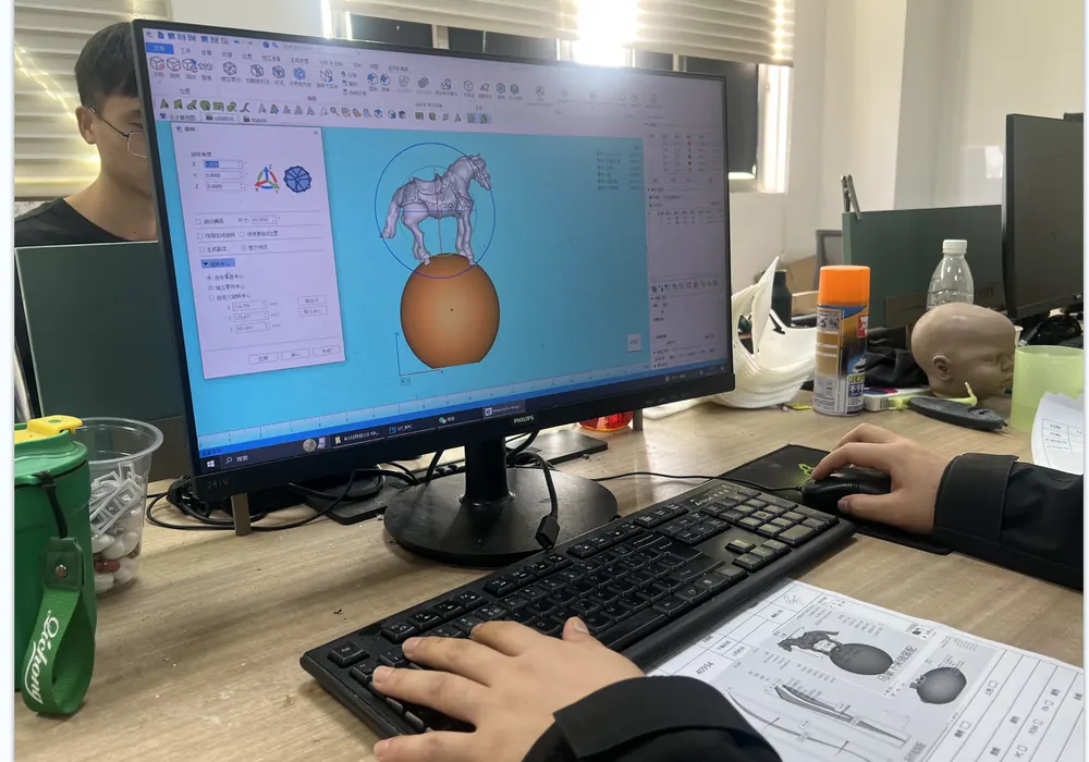
Set practical parting lines, draft, ejection contact areas, undercut treatments, and side-action requirements around geometry, cosmetic zones, and critical interfaces.
Review gate position, flow path, wall transitions, venting, knit-line risk, and cooling approach to support stable prototype injection molding.
Align cavity layout, mold base, inserts, safe-to-modify areas, and modular features with expected design changes, target quantity, and sampling priorities.
Translate critical dimensions, datums, visible surfaces, material requirements, and functional interfaces into clear tooling, sampling, and inspection priorities.
Technical Capability
Prototype tooling capability is defined by part geometry, resin behavior, tool construction, planned quantity, surface requirements, validation objectives, and inspection needs.
| Tooling Approach | Prototype molds, bridge tools, interchangeable insert systems, and project-specific tooling concepts are selected around the validation plan and expected next-stage requirements. |
|---|---|
| Part Geometry | Parting lines, draft, undercuts, side features, cores, wall transitions, ribs, bosses, gates, and ejection are reviewed from the supplied CAD and drawings. |
| Tool Materials | Aluminum and pre-hardened steel are common prototype tooling options. Material selection depends on the resin grade, abrasive or filled content, surface requirement, planned sample quantity, and expected revisions. |
| Molded Materials | Common and engineering thermoplastics, including ABS, PC, PC/ABS, PP, PA, POM, PBT, and selected filled or flame-retardant grades, are reviewed against functional, processing, and availability requirements. |
| Surface Requirements | Texture, polish level, visible surfaces, gate placement, parting-line location, ejector witness limits, and secondary finishing requirements should be defined before tool manufacture. |
| Secondary Operations | Threaded insert installation, machining of critical features, marking, painting, assembly, dimensional inspection, and project-specific finishing can be planned with the molded-part workflow. |
| Quantity Planning | Tool construction and molding plans are aligned with required samples, pilot quantities, expected revision cycles, and any controlled bridge-production requirement. |
| Lead Time | Project timing is confirmed after CAD review, DFM, tool construction, resin availability, mold trials, finishing, inspection, and delivery requirements are defined. |
Validation Loop
Each prototype mold trial is a controlled validation cycle. Documented process conditions create representative samples, while measured findings guide part, tool, or process decisions before the next build.
Establish an initial molding window around the approved resin, filling, packing, cooling, and part-release conditions.
Produce prototype molded samples under documented conditions for dimensional, surface, assembly, and functional review.
Compare critical dimensions, interfaces, visible surfaces, defects, and functional observations against the agreed requirements.
Determine whether the required adjustment belongs in the part design, tool feature, molding process, or inspection method.
Approve the sample for the next project stage, or define the focused changes and evidence required for the next sampling round.
Repeat only where the sample data shows a defined improvement is required. Talk to Our Engineers ↗
Design Notes
Plan draft on walls, ribs, bosses, and textured faces to support reliable release and limit drag marks during ejection.
Plan for releaseUse controlled wall-thickness transitions to support material flow, packing, cooling, shrinkage control, and part stability.
Control wall transitionsPlace tool splits with consideration for flash control, visible surfaces, sealing faces, functional interfaces, and practical mold construction.
Protect key facesIdentify undercuts, side holes, clips, and retention features early so a suitable insert, side-action, or design-change strategy can be evaluated.
Review side featuresBalance structural support with moldability by reviewing attachment geometry, local wall transitions, material flow, cooling, sink risk, and ejection.
Balance structural detailsSelect gate locations around flow length, feature filling, knit-line risk, warpage direction, trimming access, and cosmetic-surface priorities.
Guide material flowReserve adequate ejection contact areas and keep ejector witness locations away from critical cosmetic or functional surfaces where practical.
Plan ejection earlyIdentify critical dimensions, datums, and functional relationships instead of applying uniform limits to every feature. Align requirements with resin behavior, geometry, and inspection method.
Prioritize what mattersFlag likely design changes during early review so interchangeable inserts, safe-to-modify areas, or flexible tool construction can be considered.
Design for iterationTypical Parts


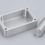
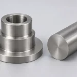
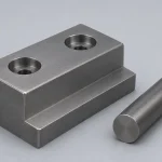
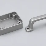
From housings and covers to clips and connectors, prototype injection molded parts bring production-intent features into physical form. Evaluate fastening, component alignment, handling, and surface details using the selected molding resin.
Secondary Operations
 SPI Finish
Mold surface grades for specifying gloss and texture on injection-molded parts.
 Polishing
Mechanical polishing for smoother surfaces and satin, bright, or mirror finishes.
 As Machined
CNC machined surfaces retaining tool marks without additional cosmetic finishing.
 Sand Blasting
Abrasive blasting for matte textures and metal surface preparation before coating.
Applications

Custom automotive parts for prototypes and low-volume production.
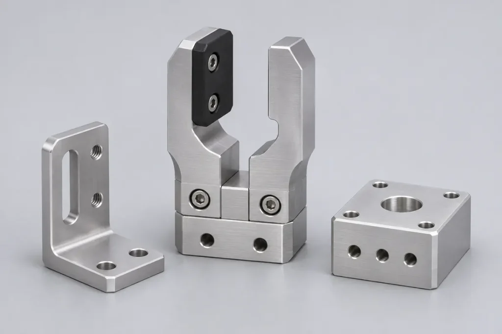
Custom robotic parts, fixtures, and automation equipment components.
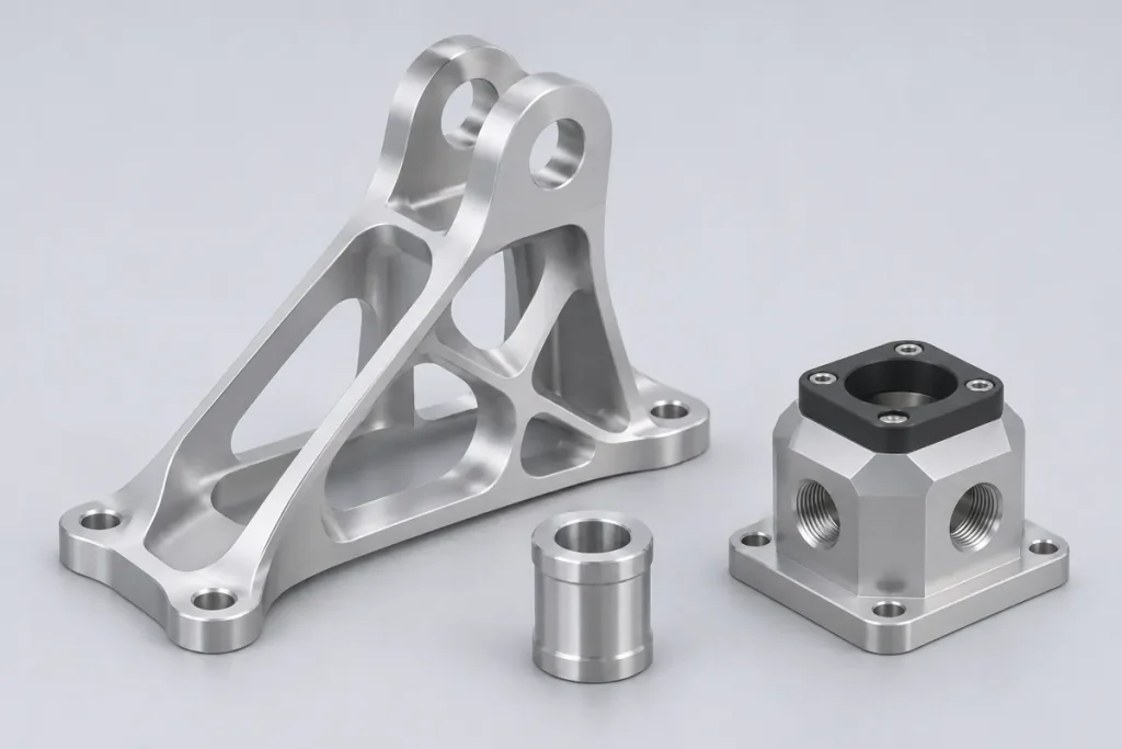
Aerospace prototypes and custom parts for engineering evaluation.

Medical device prototypes, custom housings, and mechanical components.
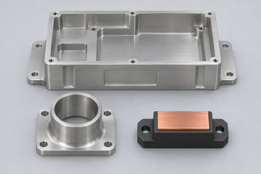
Custom energy equipment parts, housings, and mounting components.
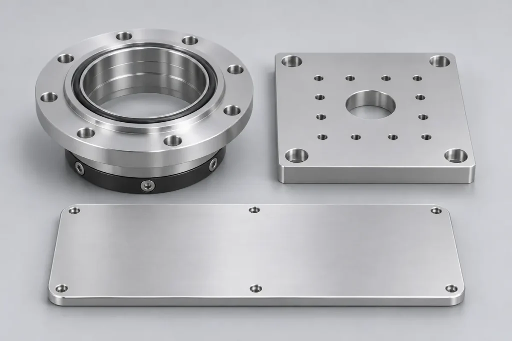
Custom semiconductor equipment parts, fixtures, and handling components.

Custom parts and prototypes for printers, copiers, and scanners.
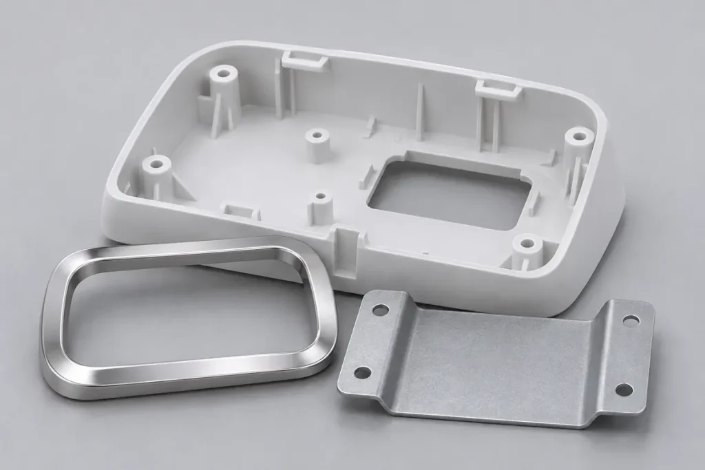
Custom appliance parts and enclosures for product development.
Quality Control
Review prototype molds and injection molded samples against approved drawings and acceptance criteria. Check critical dimensions, resin identification, assembly interfaces, and visible surfaces, with inspection records and any agreed deviations documented for delivery.
Tooling Selection
| Comparison | Prototype Tooling | Production Tooling |
|---|---|---|
| Primary Purpose | Validate molded part design, material selection, fit, and function before production release. | Manufacture approved parts repeatedly to defined quality, output, and service-life requirements. |
| Production Scope | Engineering samples, pilot builds, and selected bridge-production runs. | Recurring production at low, medium, or high volumes, according to expected demand. |
| Tool Materials | Commonly aluminum or pre-hardened steel, selected for resin, sampling needs, and expected revisions. | Pre-hardened or hardened tool steel; aluminum may suit selected production programs. |
| Tool Construction | Cavity layout, cooling, ejection, and manual or automatic actions are chosen for the validation scope. | Cavity layout, runners, cooling, wear components, and automation are engineered for sustained output. |
| Lead Time | Often shorter when construction and qualification requirements are simpler. | May require more time for durable construction, automation, trials, and production qualification. |
| Design Changes | Planned revisions can be supported through replaceable inserts and reserved machining allowance. | Changes remain possible; effort depends on affected features, tool material, and requalification needs. |
| Tool Life | Specified for the expected sampling and bridge-production cycles. | Specified for recurring production, with maintenance and component replacement considered. |
| Cost Profile | Often lower initial investment when tooling complexity and expected output are limited. | Often higher initial investment; cavity output, cycle time, maintenance, and volume determine total cost per part. |
Not sure which route fits your project? Talk to an Engineer.
FAQ
It produces molded samples for checking design, material performance, fit, and function before production tooling is finalized.
Yes, subject to resin availability and compatibility with the proposed mold and processing conditions.
Many changes are possible. Feasibility depends on the affected geometry, tool construction, and available machining allowance.
Provide 3D CAD, available drawings, resin requirements, sample quantity, and critical dimensions or cosmetic requirements.
Yes, when the agreed tool life, resin, part requirements, and planned quantity support continued use.
Upload your CAD files and drawings for an engineering review and project-specific quotation.




 Confidential File Handling
 Global Delivery